[¤3] In Phases B, C, and D a number of different architectural views are considered and used to build up a model of the new architecture. At XYZ, the Architectural Model level was developed in the following steps:
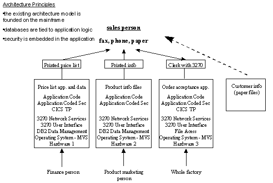
[¤12] In executing step 1 the existing architecture was assessed:
[¤17] Figure J-6: Existing Architecture in TOGAF Terms
[¤18] Notice how in Figures J-6 and J-7 the legacy systems supporting the Price list, Product Info and Order Acceptance applications are easy to handle as monolithic building blocks. Figures J-8, J-9 and J-10 show how they can be connected to new building blocks using adapters.
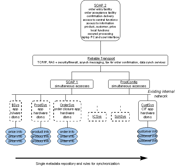
[¤19] In step 2 the function view was examined based upon what the system was intended to do, and how it should behave. The function view was depicted in the following figure. Note that the Inventory Control and Scheduling System are not covered.
[¤21] Figure J-7: Future Architecture of Functions
[¤22] In executing step 2 a view of the future architecture was created by processing the technical functionality that must be provided and by:
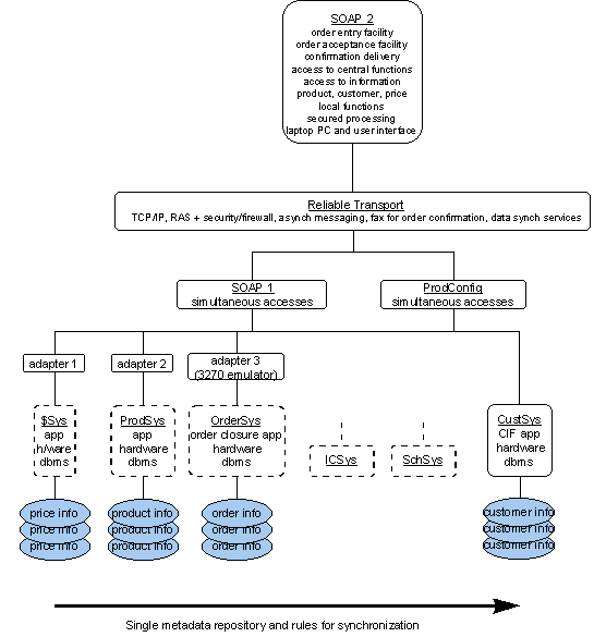
[¤34] Figure J-8: Augmented Future Architecture of Functions
[¤35] The future architecture diagram (Fig J-8) shows how the constraints identified in the earlier technical functionality and constraints work have been incorporated. It was necessary to retain the existing systems for order handling and product information. The initial constraint list also included retaining the existing system for customer information, but this was overridden by the need to improve the quality of the sales process and a new system is proposed to deal with this. Return on investment is the driving force behind the decision to retain the existing system for price data. Quality problems with the price system highlighted in Figure J-3 will be resolved through a single metadata definition and rules for synchronization as shown in Figure J-7. These legacy systems are integrated into the new SOAP (Sales Order Application) by developing adapter software. The following describes the SOAP application.
[¤56] To ensure that building blocks are as reusable as possible, detailed information is needed about the building block. For this reason it is helpful to take views of individual building blocks and not just of the complete system. For the maximum benefit, it may be necessary to take views of both ABBs and SBBs.
[¤57] It is the responsibility of the architect to foresee the integration of any application with the rest of the enterprise regardless of the isolated position of the application today. This future integration is facilitated by complete definition of building blocks. It is the responsibility of the business unit to implement in accordance with the rules of the architecture.
[¤58] Step 3 consists of creating an architecture model of building blocks. The figure above depicts a future architecture model of functions, but does not express the relationships and interfaces between the elements in the architecture model. As the architectural development process continues, it becomes important to define a manageable granularity for building blocks and to fully define their linkages. Without this work there is no guarantee of interoperability between the various building blocks chosen.
[¤59] We have identified two lists of candidate building blocks in the above steps. Prior to building a model of building blocks these lists are processed and some candidates become recommended building blocks.
| [¤60] Candidate Building Blocks - [¤61] Business Process Driven List |
[¤62] Candidate Building Blocks - [¤63] Baseline Driven List |
| [¤64] sales person's laptop | [¤65] price list application, data and platform |
| [¤66] sales person's CIPR | [¤67] product information and platform |
| [¤68] sales person's LIPR | [¤69] order acceptance application, data and platform |
| [¤70] ProdConfig | [¤71] |
| [¤72] ICSys | [¤73] |
| [¤74] SchSys | [¤75] |
| [¤76] $Sys | [¤77] |
| [¤78] OrderSys | [¤79] |
[¤80] Table J-2: Candidate Building Blocks - Lists
[¤81] The process of identifying building blocks includes looking for collections of functions which require integration to draw them together or make them different.
[¤82] First it is recommended that the candidate building blocks from list B be selected as building blocks because they are reusable legacy items. With these a building block containing all the adapters is identified given the affinity of similar logic, e.g. providing the network adapter functionality on behalf of all the legacy applications.
[¤83] Next a network building block appears to be required as it is a new network that must be built or purchased and is independent of the applications implemented. It itself can be a reusable building block for other applications.
[¤84] The laptop with the SOAP 2 application is identified as a building block because it is a modular pack of functionality specially built with applications and data tightly integrated for the mobile sales force. However a RAS-capable firewall was also identified as a separable building block.
[¤85] The new customer information system is also identified as a reusable building block given its applicability across applications past, new and future. The SOAP 1 and configuration systems were identified as two additional building blocks.
[¤86] We depict the architecture building blocks at a high level in the following diagram.
[¤88] Figure J-9: Representation of XYZ SOAP system
[¤89] Figure J-9 presents a relationship view of the system. Compare this with Figure J-8, a functional view, to see how different diagrammatic views of the same system can be used to show different things.
[¤90] In executing step 3 the future architecture was created by processing the technical functionality that must be provided and:
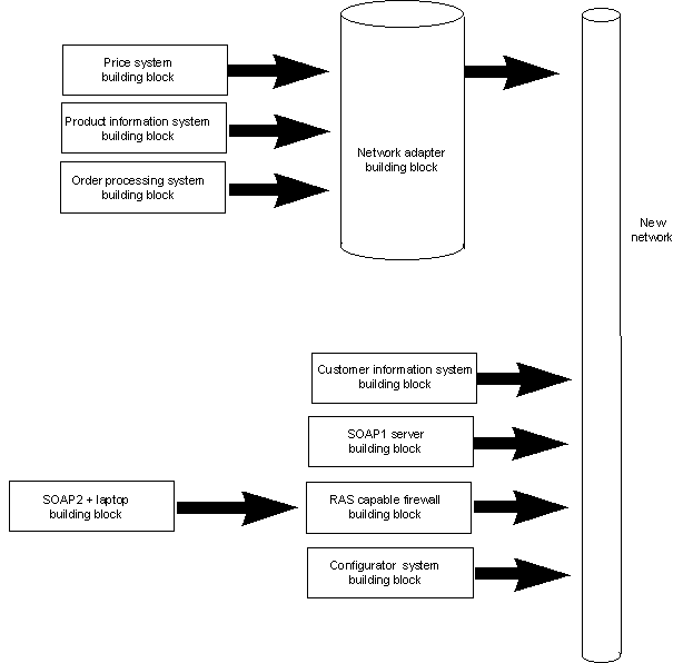
[¤93] Step 4 is to select the services portfolio required per building block. The following depicts the services mapped to component in the architecture model.
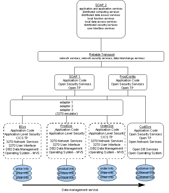
[¤95] Figure J-10: Services Map
[¤96] Step 5 in the process is to confirm that the architecture supports the business goals and objectives. This is a relatively subjective task of answering the questions developed in step 1. In this example we did not establish a set of questions that would be used to test the architecture, but one could easily envision such questions and how to pose those questions in light of the architecture. For example one question could be "does the architecture prohibit the immediate processing of an order by a customer?" which would be answered "no" in our case above.
[¤97] The use-cases developed earlier are a handy tool to test the completeness and applicability of the architecture and its building blocks.
[¤98] Building block specifications should be recorded in detail. Here is an example of a building block specification document.
[¤99] Where an enterprise architecture exists or is being developed, it may be valuable at this point to review the new set of building blocks. Anything of benefit to the wider enterprise should be abstracted back to an architectural level and then fed back into the enterprise architecture development process.
[¤100] Step 8 is to conduct a gap analysis, and is not covered in this example.
[¤101] The Opportunity Identification level
[¤102] Copyright © The Open Group, 1998, 1999, 2002