Using TOGAF to Define and Govern Service-Oriented Architectures – Using TOGAF for Enterprise SOA
An effective enterprise architecture is critical to business survival and success, and is the indispensable means to achieving competitive advantage through IT. TOGAF is a detailed method and a set of supporting tools for developing enterprise architectures. It codifies the good practice that has evolved in the work of enterprise and IT architects over many years. It will help the architect to decide where and how to use SOA.
The TOGAF Architecture Development Method (ADM) breaks the complex process of architecture development into a number of simpler steps, or phases, in which the architect considers different aspects of the overall problem:
- The Preliminary Phase
- Architecture Requirements Management
- Phase A: The Architecture Vision
- Phase B: The Business Architecture
- Phase C: The Information Systems Architectures (Applications and Data)
- Phase D: The Technology Architecture
- Phase E: Opportunities and Solutions
- Phase F: Migration Planning
- Phase G: Implementation Governance
- Phase H: Architecture Change Management
Those familiar with TOGAF will recognize the following graphical depiction of the ADM:
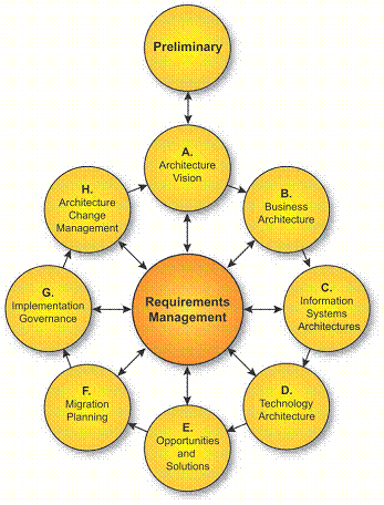
TOGAF Architecture Development Method (ADM)
This section describes, for each phase of the TOGAF ADM, what the architect should consider particularly when looking to apply the principle of service-orientation, and how this affects the outputs of the phase. In short, it explains how to use TOGAF to do SOA.
This is not a self-standing description. It assumes knowledge of TOGAF, and leaves out everything that is not related to SOA. To follow it, the architect must know about TOGAF. The architect can find all the information needed on the TOGAF website.
The Preliminary Phase
The TOGAF Preliminary Phase is about defining “where, what, why, who, and how we do architecture” in the enterprise concerned. It does the preparation and establishes the architecture framework needed for new enterprise architecture work. TOGAF provides for incremental architecture development. Each cycle through Phases A to H creates an increment to the enterprise architecture. (The cycles typically overlap, with Phases A to F of each new cycle being carried out in parallel with Phase G: Implementation Governance of the previous cycle.) The Preliminary Phase does what is needed before the cycles can start. It is usually carried out when TOGAF is first adopted by a particular architecture team for a particular enterprise. Its activities may be re-visited as needed for subsequent architecture engagements.
The Preliminary Phase is where the architect adopts the principle of service-orientation. This affects two other outputs of the phase: the governance and support strategy, and the content of the initial Architecture Repository.
The Principle of Service-Orientation
The starting point for SOA development with TOGAF is that the enterprise adopts service-orientation as an architecture principle.
Architecture principles define the underlying general rules and guidelines for the use and deployment of all IT resources and assets across the enterprise. They reflect a level of consensus among the various elements of the enterprise, and form the basis for making future architecture decisions. The Preliminary Phase defines the architecture principles that will form part of the constraints on any architecture work undertaken in the enterprise. They are typically developed by the lead enterprise architect, in conjunction with key stakeholders, and are approved by the Architecture Board. They are included in the tailored architecture framework, which is an output of the Preliminary Phase.
TOGAF Version 9 has an example set of architecture principles, which includes a principle of service-orientation, as number 6 in the Business Principles examples:
Principle |
Service-Orientation |
Statement |
The architecture is based on a design of services which mirror real-world business activities comprising the enterprise (or inter-enterprise) business processes. |
Rationale |
Service-orientation delivers enterprise agility and Boundaryless Information Flow. |
Implications |
Service representation utilizes business descriptions to provide context (i.e., business process, goal, rule, policy, service interface, and service component) and implements services using service orchestration. Service-orientation places unique requirements on the infrastructure, and implementations should use open standards to realize interoperability and location transparency. Implementations are environment-specific; they are constrained or enabled by context and must be described within that context. Strong governance of service representation and implementation is required. A ‘‘Litmus Test’’, which determines a ‘‘good service’’, is required. |
An enterprise wishing to use TOGAF for SOA should include this principle, either as it stands or in modified form, in its set of architecture principles.
If the architect is introducing TOGAF to an enterprise that is already committed to SOA, or that is part of a larger enterprise that has made a strategic decision to use SOA, then adoption of the principle of service-orientation is a given. If, on the other hand, the architect is introducing SOA to an enterprise that is not already committed to it, then the decision to adopt this principle should not be taken lightly.
SOA Maturity Assessment
Successful SOA depends in part on the readiness of the enterprise to become service-oriented. The architect can conduct an SOA maturity assessment during the Preliminary Phase, using The Open Group Service Integration Maturity Model (OSIMM) described in the SOA Source Book as part of the review of the organizational context for conducting enterprise architecture. This will help to establish the rationale for the enterprise to adopt the principle of service-orientation. OSIMM examines seven areas of maturity and helps to categorize these into seven levels of maturity. Graphically, it is briefly depicted as follows:
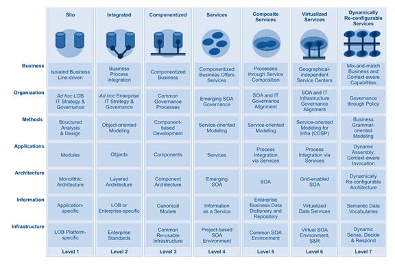
OSIMM will help identify the organization’s SOA level of maturity, but more importantly, it can identify where the organization needs to be to adopt the principle of service-orientation. The gaps between the current state of the organization and where it wants to be can often be readily described.
As with the introduction of any significant new idea, it is good to start with a small project, and learn from experience, before implementing on a wide scale. The architect can undertake a complete but rapid TOGAF cycle, provisionally assuming service-orientation, without spending too much effort on detailed analysis, to define a pilot SOA project. Successful implementation of that project will then lead to final adoption of the principle and close off any maturity assessment gaps identified over time.
From here on we assume that the principle of service-orientation is adopted.
Governance and Support Strategy
TOGAF does not attempt to describe all aspects of implementation and operational governance, only those areas directly related to the architecture under development. It assumes that detailed governance for those areas is in place. The Preliminary Phase includes confirming the architecture governance and support strategy, as part of the Organizational Model for Enterprise Architecture. The architect should review the existing governance procedures, and confirm that they are appropriate for SOA. If they are not, then the architect should make recommendations for changing them.
It may not be appropriate to undertake the detailed development of governance rules and procedures as part of the Preliminary Phase. It could be better to confirm the architecture governance procedures (which are not much affected by SOA), and to commission a separate project to define implementation and operational governance procedures before implementation starts.
Since SOA governance is considered critical to its success and as an aid to the enterprise architect, The Open Group SOA Work Group has developed a governance framework that focuses on SOA and may be used to enhance existing governance frameworks. A summary of The Open Group SOA Governance work is available as part of the SOA Source Book, as is the detailed SOA Governance Technical Standard.
A high-level view of how SOA governance extends and supports both enterprise architecture and IT governance is given below.
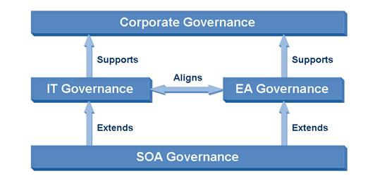
SOA Governance Supports IT and Enterprise Architecture Governance
There is also a Governance Reference Model that is depicted below.
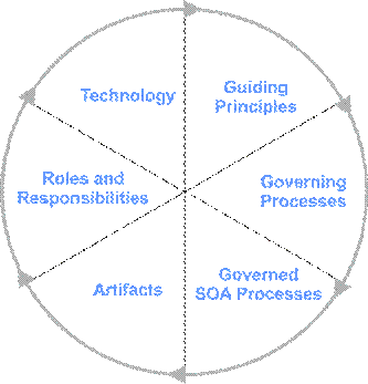
SOA Governance Reference Model
In addition to describing in detail the various aspects of SOA governance, the model also suggests a “Vitality Method” (SGVM) which is a process that utilizes the SOA Governance Reference Model (SGRM) as a baseline and then follows a number of phased activities to customize this baseline model to cater to the organization’s variants. SOA governance should be viewed as a process and not a project; therefore, the phases of the SGVM should be viewed as a continuous improvement loop, whereby progress is measured, and course-correction and updates to the SOA Governance Regimen and SOA Governance Roadmap are performed when needed. The figure below is a high-level graphic of the SGVM:
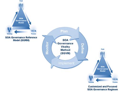
SOA Governance Vitality Method
Initial Architecture Repository and the SOA Reference Architecture
The enterprise's Architecture Repository contains a collection of models, patterns, architecture descriptions, and other artifacts that are available for the development of its architectures. They may result from previous architecture work in the enterprise or from work in other enterprises, or in industry bodies. The Preliminary Phase of TOGAF includes the establishment of an Architecture Repository with an initial collection of material.
The SOA Work Group has compiled numerous materials that may be relevant in initially populating the Architecture Repository. The Source Book (first edition) describes the Service-Oriented Architecture (SOA) Reference Architecture, which is a significant underlying logical structure for the development and assessment of architectures designed and built using a combination of traditional and service-oriented computing principles and concepts. It contains the following sections:
- The Building Blocks of SOA, which describes a set of architecture building blocks that represent the key elements of SOA
- The SOA Reference Architecture, which gives an overview of the nine layers of the reference architecture, with examples and rationale describing the main responsibilities of the layers and their primary building blocks
- Detailed Building Blocks of the SOA Reference Architecture, which presents detailed models that show how some of the features of SOA can be implemented using the reference architecture
- Infrastructure for SOA, which describes architecture building blocks that correspond to infrastructure products that are available today to support service-oriented applications
A summary graphic that describes the SOA Reference Architecture follows:
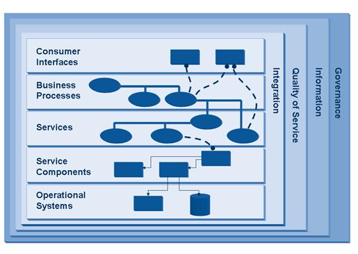
The nine “layers” are described as follows:
Operational Systems Layer:
- Programs and data of the operational systems of the enterprise
- The new and existing infrastructure needed to support the SOA solution
Service Components Layer:
- Software components, each of which provides the implementation or “realization” for a service, or operation on a service, and binds the service contract to the implementation of the service in the operational systems layer
Services Layer:
- Services, with their descriptions, contracts, and policies, and the containers that contain the service components
Business Processes Layer:
- Business processes , and compositions in which business processes are composed of other business processes and of services
Consumer Interfaces Layer:
- The programs by which the users interface to the services
Integration Layer:
- Integration of and communication between other building blocks, including messaging, message transformation, complex event processing, service composition, and service discovery
Quality of Service Layer:
- Monitoring and management of the quality of service of the architected system, including its performance, reliability, availability, scalability, security, and manageability
Information Layer:
- Management, analysis, interpretation, and transformation of data
Governance Layer:
- Governance rules and procedures
- Services and programs that support the application of the rules and the operation of the procedures
Partitions & Centers of Excellence: Establishing the Architecture “Team”
TOGAF establishes the Architecture Team and Organization – team structure, roles, responsibilities, etc. – in the Preliminary Phase to support a desired architecture capability. With SOA we suggest a specific method of establishing that architecture capability: the SOA Center of Excellence (CoE).
Different teams will work on different elements of architecture at the same time. Partitions allow for specific groups of architects to own and develop specific elements of the architecture (see partitions and scoping in Phase A). It is suggested that the team start with a focused initiative before implementing on a wide scale.
The team responsible for SOA should initially be structured as a CoE.
A successful CoE will have several key attributes:
- A clear definition of the CoE’s mission: why it exists, its scope of responsibility, and what the organization and the architecture practice should expect from the CoE.
- Clear goals for the CoE including measurements and key performance indicators (KPIs). It is important to ensure that the measures and KPIs of the CoE do not drive inappropriate selection of SOA as the architecture style.
- The CoE will provide the “Litmus Test” of a good service.
- The CoE will disseminate the skills, experience, and capabilities of the SOA CoE to the rest of the architecture practice.
- Identify how members of the CoE and other architecture practitioners will be rewarded for success.
- Recognition that, at the start, it is unlikely the organization will have the necessary skills to create a fully functional CoE. The necessary skills and experience must be carefully identified, and where they are not present, acquired. A fundamental skill for leading practitioners within the CoE is the ability to mentor other practitioners transferring knowledge, skills, and experience.
- Close-out plan for when the CoE has fulfilled its purpose.
Summary
In summary, when developing the TOGAF Preliminary Phase, there are a number of methods, tools, and reference materials that have been developed by the SOA Work Group to help the enterprise architect develop their Service SOA. These include:
- Principles: service-orientation
- Determining orgainization readiness for SOA: OSIMM
- Governance: The Open Group SOA Governance Model and Vitality Method
- Adapting Reference Architectures to the Organization: The SOA Reference Architecture
- Establishing a SOA Center of Excellence (CoE) as an initial “footprint”
Phase A: The Architecture Vision
The Architecture Vision phase is concerned with establishing the architecture project and obtaining approval to proceed.
This phase captures the scope of the architectural initiative, which depends on the nature of the enterprise and the level of detail of implementation specification. It creates a compelling vision of what the organization will have at end-of-job, after all the projects necessary to instantiate the architecture have been completed. And it identifies the key stakeholders, concerns, and business requirements.
The Nature of the Enterprise
The scope of an enterprise architecture development depends on the size and structure of the enterprise.
TOGAF defines “enterprise” as any collection of organizations that has a common set of goals. For example, an enterprise could be a government agency, a whole corporation, a division of a corporation, a single department, or a chain of geographically distant organizations linked together by common ownership. An “enterprise architecture” can encompass all of the information and technology services, processes, and infrastructure of an entire enterprise, or just cover a specific domain within an enterprise. In both cases, the architecture crosses multiple systems and functional groups.
The size and complexity of an enterprise affects the way the enterprise architect develops its architecture. Where there are many different organizational and business models, it is not practical to integrate them within a single architecture. There are very few infrastructure items, such as the Internet and the World-Wide Web, that can be applied across the whole of a large organization and they provide only a basic level of support for business processes. It is therefore generally not appropriate to develop a single, integrated SOA for a large and complex enterprise.
For such an enterprise, the architect should look first at developing a strategic architecture that gives a summary formal description of the enterprise, providing an organizing framework for operational and change activity, and an executive-level, long-term view for direction setting. This might, for example, identify particular segments where SOA should be used, and call for use of standards for interaction between segments, but it is highly unlikely to specify particular services or groups of services, or to prescribe a detailed infrastructure for SOA. The architect could then develop segment architectures, each of which gives a detailed, formal description of areas within an enterprise, used at the program or portfolio level to organize and align change activity. Each of these segment architectures could be a single, integrated SOA. This concept is depicted below.
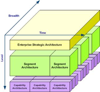
Scoping the Enterprise Architecture
For a smaller and less complex enterprise whose business operations can share a common infrastructure, the architect can use TOGAF to create an integrated SOA with groups of services that support the business activities.
From here on we assume that the scope is an enterprise of this kind. It could be self-standing or a segment of a larger enterprise.
Level of Detail of Implementation Specification
How completely should the architecture define the implementation? At one extreme, it could specify all of the systems to be produced, define all the projects that will produce them, and create a detailed time plan for those projects. At the other extreme, it could just indicate areas where work is needed, and suggest priorities for addressing them.
An SOA development could fall anywhere between these two extremes. For the kind of enterprise SOA that we are considering here, it is likely that the architect would specify the infrastructure and define the projects to implement it, with a detailed time plan. The architect might do the same for some or all of the solutions. Alternatively, particularly where agility is important, the architect might identify solutions, and perhaps specify initial versions of them, but allow for additional solutions to be identified later, and for implementation projects to develop further versions of the solutions without having to ask for changes to the architecture.
In the first case, solution project definition and planning is carried out in TOGAF Phase E (Opportunities and Solutions) and Phase F (Migration Planning), and the architecture team has a supervisory role for those projects in Phase G (Implementation Governance). In the second case, the architecture team supervises solution project definition and planning, other than for those specified initially, in Phase G rather than doing that definition and planning in Phases E and F. (This, however, is not the TOGAF preferred methodology.)
Where the architecture does not specify all solutions in detail, the architect may wish to create an architecture that provides a detailed definition of common infrastructure that can be referenced by solution developments. There is a subtle distinction between such an architecture – an enterprise reference architecture – and an enterprise architecture. The enterprise architecture applies to a whole enterprise and identifies its components. The enterprise reference architecture applies to each of the components of the enterprise and describes aspects that they have in common. The architect would produce the enterprise reference architecture in parallel with the enterprise architecture, but as a separate set of artifacts. The Open Group SOA Work Group Reference Architecture, referred to above, is an example of a potential enterprise reference architecture.
The Vision
The Architecture Vision includes a high-level description of the final architecture that is envisaged.
There is an obvious difference between an SOA architecture description and a description of an architecture of another style. The SOA description uses different language, with words such as “service”, “composition”, and “contract”, and it has different models, such as matrices showing use of services by business processes and use of applications by services. The recently published SOA Ontology can provide taxonomical and ontological assistance with the language of SOA.
Although it may not include the kinds of detailed model produced in Phases B, C, and D, the high-level description produced in Phase A will reflect the service-oriented nature of the architecture that is envisaged.
Stakeholders, Concerns, and Business Requirements
Phase A is followed by the three TOGAF phases that produce detailed architecture descriptions for the Architecture Definition Document. In each of these phases, the architect:
- Develops models of the target system in the light of requirements
- Discusses concerns with stakeholders, using views of the system that are derived from the models
- Refines the models
- Identifies further requirements to be addressed
This is an iterative process, repeated until the architect is satisfied that the concerns relevant to the phase have been discussed and the requirements relevant to the phase are addressed.
The requirements to address, the stakeholders to consult, and the models and views to develop vary from one architecture engagement to another. In Phase A of each engagement the architect identifies the key stakeholders and their concerns, states the key business requirements to be addressed, and considers which architecture views and viewpoints to develop.
There are concerns that are peculiar to SOA, or are more likely to arise in SOA developments. The Addressing Stakeholder Concerns in SOA section of the SOA Source Book (first edition) lists some areas of concern that the architect is likely to encounter.
For additional information, see Appendix A. This describes changes to the standard TOGAF 9 Inputs, Steps, and Outputs appropriate for SOA. It also highlights areas of emphasis that the architect doing SOA should especially consider.
TOGAF 9 Architecture Development (Phases B, C, and D)
In this section we consider the SOA impact on Phases B, C, and D, the TOGAF architecture development phases.
The figure below depicts the TOGAF 9 Meta-model and its entity relationships. TOGAF is already well suited for the adoption of SOA as it takes a service-centric approach to developing its architecture domains. Here we specifically identify (outlined in red) those TOGAF entities that already align with the SOA Work Group concepts.
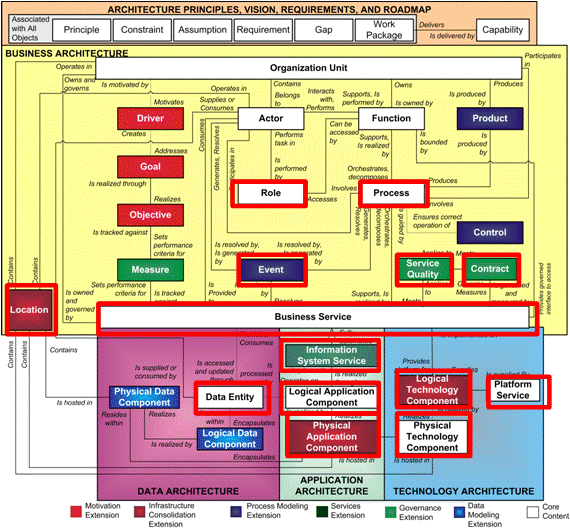
TOGAF 9 Meta-Model with Key SOA Entities Highlighted
Key entities include:
- Event
- Process
- Business Service
- IS Service
- Platform Service
- Logical Application and Technology Component
- Physical Application and Technology Component
- Data Entity
- Service Quality
- Contract
- Location
- Information Entities
- Logical Information Components
Extensions of the meta-model are typically necessary to fully support SOA.
The next figure uses the TOGAF 9 conventions of “extensions” to describe additional meta-model entities that the architect should consider when developing SOAs. Each SOA “extension” will be described in the following ADM phase sections. In addition, for each domain is a description of artifacts that are appropriate for the enterprise architect’s development of an SOA.
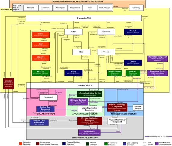
TOGAF 9 Meta-Model with Relationships Updated with SOA Extensions
New and updated meta-model objects:
Extension Term |
Description |
Information Entity |
Information communicated about within the business. |
Information Component |
An ideal grouping of Information Entities fulfilling one or more principles. These will be the base for the structure of the SOA Information Exchange Model (Canonical Information Model). |
IS Service Contract |
An agreement between an IS service consumer and an IS service provider that establishes functional and non-functional parameters for interaction. |
SOA Solution |
The requirements and architecture (structure) of the entire solution including process, information, service, and infrastructure requirements. |
Service Quality |
Used as an attribute to services, components, and contracts. Defines the non-functional requirements. |
Location |
Used as an attribute to a service or component. |
New and updated relations between meta-model objects:
Meta-Model Objects Involved |
Relationship Name |
Description |
Process Business Service |
Consists of |
The Process consists of a set of Business Services and their related contracts. |
IS Service Logical Application Component |
Is realized through |
IS Services are structured into Logical Application Components (SOA services). The structuring criteria are derived from the long-term strategies of the organization. |
Business Service Contract Information Entity |
Describes interaction with |
The Information Entity describes the information passed in the contract (relation) between two business services. |
IS Service Contract IS Service |
Drives requirements for |
The IS Service Contract drives the requirements of the IS Service by formalizing the functional and non-functional characteristics of IS Service interaction with other services, external applications, or users. |
IS Service Contract Business Service Contract |
Is derived from |
The IS Service Contract derives its specification from the Business Service Contract and must in no way contradict or inhibit the Business Service Contract from being fulfilled. |
Information Entity Information Component |
Consists of |
The Information Component is a structuring of Information Entities. The structuring criteria are derived from the long-term strategies of the organization. |
Information Entity Data Entity |
Influences |
The Data Entities are derived from the Information Entities. |
Information Component Logical Data Component |
Influences |
The Logical Data Components are derived from the Logical Information Components. |
IS Service Data Entity |
Operates on |
The IS Service operates on Data Entities. Data Entities represent the data used internally in a IS Service. |
Logical Application Component Logical Data Component |
Operates on |
The Logical Application Component operates on Logical Data Components. The Logical Data Components are the internal data structures proposed in an SOA Service (Logical Application Component on capability level). |
Logical Application Component Logical Technology Component |
Requires |
The Logical Application Component (SOA service requirements on capability level) requires some Logical Technology Components on which to run. |
Logical Application Component Physical Application Component |
Is realized by |
The Physical Application Component explains with what the Logical Application Component should be implemented (e.g., wrapping of existing functionality or a new development). |
SOA Solution Physical application Component |
Consists of |
The SOA Solution consists of a set of Physical Application Components. |
SOA Solution Physical Technology Component |
Utilizes |
The SOA Solution utilizes Physical Technology Components (SOA infrastructure; e.g., ESB, BPEL executors, registry, repository, etc.). |
The table above takes a “TOGAF-centric” focus and is very appropriate for those architects familiar with TOGAF. Note that we will use a “UML-like” diagram in each of the following phases that take an “SOA architect” focus for those who may not be intimately familiar with TOGAF, but will, hopefully, enlighten them to the advantages of utilizing the TOGAF framework. The complete “UML-like” diagram is shown in the SOA-TOGAF Meta-Model.
Phase B: The Business Architecture
The Business Architecture aligns the enterprise's business processes, people, operations, and projects with its overall strategy, providing a foundation on which to build the Information Systems Architectures and the Technology Architecture. This is the first of the three TOGAF phases that produce detailed architecture descriptions for the Architecture Definition Document.
The TOGAF 9 meta-model has been extended to include an SOA-specific “Information Entity” from which the Business Vocabulary Catalog and an Information Component Model are derived. This is depicted below.
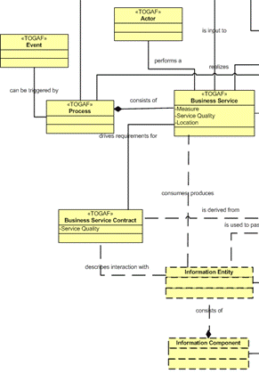
Phase B: Business Architecture Meta-Model Detail
In addition, the importance of the existing “contracts” takes on significantly more importance in SOA. Contracts formalize the functional and non-functional characteristics of a business service interaction with other business services, external applications, or users. The contract details the information exchanged and associated non-functional requirements such as response times and availability. The non-functional requirements are modeled using the Service Quality object. The contracts are used to collectively define the Service Quality objects including the functional and non-functional requirements on the business services.
A Process is a set of Business Services and their contracts. One Business Service can participate in more than one Process.
The starting point for the artifacts that are developed in this phase is the set of key business requirements identified in Phase A and further detailed in this phase. For the kind of enterprise SOA that we are discussing here, the architect should consider the following artifacts which are particularly important for SOA because they contribute to the definition of SOA building blocks in Phase C and Phase D.
Artifact |
Purpose |
Meta-Model Entities |
Business Service Interaction Diagram |
This diagram shows all the business services in scope and their relations and the information flowing between the business services. It will indicate what business services are commonly re-used by other business services indicating opportunities for possible re-use of supporting IS services. The diagram will also be used to define business processes and the relationships between those business processes since each process is composed by a subset of this model. |
Business Services, Contracts, Information Entity |
Business Process Diagram |
This is a set of diagrams that show the business processes and their decomposition, their interactions, and the information with which they are concerned. |
Subset of business service model showing the Business Services and Contracts involved in the processes and the Business Information passed between the Business Services. |
Business Vocabulary Catalog |
This is a list of the key terms used in describing the business processes and information. It is important that the Business Architecture phase establishes the information context for the software services, as described in the Information Architecture for SOA section of the Source Book (first edition), and a catalog of business terms is an important part of this context. The architect can derive the business vocabulary while developing the business service model. |
This is a list of Information Entities and descriptions of those elements. |
Business Services Catalog |
This is a list of the enterprise's business services and their functional and non-functional requirements. It is used to analyze the non-functional requirements. |
List of Business Services and their Service Qualities |
Business Service/ Location Catalog |
To understand where the business services needs to be executed. |
Business Service, Location |
Event/Process Catalog |
To understand which process is run in relation to an event. |
Lists Events and their effected Business Process |
Contract/Service Quality Catalog |
To understand the non-functional properties of a contract. |
Lists Contracts and their relevant Service Qualities |
Business Service Interaction Matrix |
To show relations between business services. |
Business Services on both axes and Contracts in the cross-point. |
Business Service/ Information Matrix (CRUD) |
To show how information entities are used by business services and to find faults in that model. |
Business Services and Information Entities |
Information Component Model |
To define the logical structure of the information in the organization. It can be used as an input to the exchange model defining the input and outputs from SOA services. |
Information Components and their relations |
In addition, the standard TOGAF 9 models and artifacts should be considered.
It is vital that the appropriate views are produced that enable the architect to demonstrate to stakeholders how their SOA-specific concerns relating to the Business Architecture are addressed.
The level of detail of the business process analysis will depend on the circumstances of the architectural engagement. The projects that develop solutions that instantiate the architecture will perform the business analysis at the most detailed levels. It is the architect’s responsibility to select an appropriate level of detail for the enterprise architecture business analysis, first as a basis for specifying solutions, and then to enable their successful development.
In doing this the architect addresses the requirements that can be satisfied by the Business Architecture. The remaining architecture requirements will be addressed in Phases C and D.
For additional information, see Appendix A. This describes changes to the standard TOGAF 9 Inputs, Steps, and Outputs appropriate for SOA. It also highlights areas of emphasis that the architect doing SOA should especially consider.
Phase C: The Information Systems Architectures (Applications and Data)
The objectives of Phase C are to define the major types and sources of data necessary to support the business, and to define the major kinds of application system necessary to process the data and support the business.
The phase is split into two sub-phases, Data Architecture and Applications Architecture. SOA makes little difference to the Data Architecture sub-phase, but it has a major impact on the Applications Architecture.
As well as affecting the artifacts that are developed, the views that are produced, the concerns that are discussed, and the requirements that are identified, SOA affects the way that the architect does the gap analysis between Baseline and Target Architectures in Phase C.
With SOA, the traditional software applications are replaced by sets of loosely-coupled services. Existing applications should still be described, as should any new applications of a traditional kind that the architect decides is required, and these applications should be included in the applications portfolio. In addition, areas of application functionality that are covered by services should be identified. These will (probably as part of the implementation) be decomposed into services, which will be included in the services portfolio.
But SOA is not only about services, it is also the solutions created by using combinations of services. These solutions are usually structured using the Business Processes and Business Services defined in Phase B.
For SOA, as with Phase B, the Business Architecture, Phase C, the Information Systems Architecture, has extended or highlighted the TOGAF 9 meta-model to include SOA-specific relations. These include the IS Service Contract which drives requirements for related IS Services. The IS Service Contract derives its information content and non-functional requirements from the business services and business service contracts.
These are depicted below.
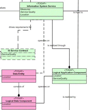
Phase C: Information Systems Architecture Meta-Model Detail
Using the artifacts described in the table below, the architect should develop views that enable the demonstration to stakeholders of how their SOA-specific concerns relating to the Applications Architecture are addressed. (Models that enable the architect to discuss concerns relating to the Data Architecture should also be developed as part of Phase C. These are similar to the models that would be developed for a traditional architecture based on software applications.)
In doing this, the architect addresses the requirements that can be satisfied by the Information Systems Architectures. The remaining architecture requirements will be addressed in Phase D, Technology Architecture.
Artifact |
Purpose |
Meta-Model Entity Usage |
IS Service Interaction Diagram |
This shows potential SOA services (IS Services) and the interactions between them, and their use of information. It is used to show the full set of requirements for the solution and the relationships between the requirements. |
IS Services and the Contracts between them. The Contracts indicate what business information is communicated. Preferably the Service Quality entity for both IS Services and Contracts are derived from the Business Services and their Contracts and related Service Qualities. |
Business Process/ IS Service Matrix |
This matrix shows the relation between each Business Process and the IS Services supporting the process. It is used to show the full set of requirements for SOA Services for a given Business Process. |
Business Process and its relation to IS Service(s) |
IS Service Contract Catalog |
The catalog lists all IS Services, their Contracts, and the related Service Qualities to enable analysis of the non-functional requirements (e.g., security, performance, loading, availability, policies, etc.) for potential SOA Services. This catalog is an important input to the Service Portfolio Management process in SOA Governance. |
List of IS Services and their related Service Qualities Additionally, IS Service Contracts for each IS Service are included. |
IS Service/ Application (existing) Catalog |
This catalog connects IS Services (potential SOA Services), Contracts, and Service Qualities with existing applications (as-is Physical Application Components). It is used to specify wrapping scenarios on existing applications and to analyze non-functional requirements. |
IS Service(s), related Contracts, and Service Qualities connected with as-is Physical Application Components |
IS Service/Data Entity Matrix |
This matrix shows what data is handled by potential SOA Services (IS Services). It is used to identify potential data handling SOA Services. |
IS Services and its related Data Entities |
Logical SOA Component Matrix |
This matrix shows the relationship between the Logical SOA Components (Logical Application Components) and the potential SOA Services (IS Services). It is used to structure Logical Components from the requirements. |
IS Services, Logical Application Components, and Principles & Business Drivers (used to find criteria to perform grouping) A Logical SOA Component (Logical Application Component) would be a candidate for an SOA Service on Capability-level architectures. |
Logical SOA Solution Diagram |
This diagram shows the relations between the Logical SOA Components (Logical Application Components) and other logical solutions (Logical Application Components). It is used to show and analyze the functional and non-functional requirements of the interfaces between solutions. |
Logical Application Components and Contracts and their Service Qualities Logical Technology Components and their mapping to Contracts are used for the interface mechanisms. |
IS Service Distribution Matrix |
This matrix shows the services distributed on physical locations to fulfill legal or other requirements. The purpose is to show and analyze whether there are any location requirements on services. This can be done on either IS Services or Logical Application Components. |
IS Service, Logical Application Component, Physical Application Component, and Location |
In addition, the standard TOGAF 9 models and artifacts should be considered.
For an enterprise architecture, these models and artifacts would typically show groups of services that support the business processes identified in Phase B, rather than individual services, and the Service Contract and Policy Catalog would list generic contracts and policies that apply to different types of service. The architect will generally leave the identification of individual services to the projects that develop solutions that instantiate the architecture.
In each of Phases B, C, and D the architect performs a gap analysis between the Baseline and Target Architectures to determine what needs to be done to move from the Baseline to the Target. For Phases B and D, and the Data Architecture sub-phase of Phase C, this is not much affected by SOA. For the Applications Architecture sub-phase of Phase C, however, SOA makes a difference to the way that the architect performs the gap analysis.
The architecture building blocks defined in Phase C will include traditional applications and groups of services covering areas of application functionality. Both kinds of building block should be included in the gap analysis. However, it may be the intent that a group of services be implemented as a “wrapper” over existing applications. This situation, which is special for SOA, should be indicated in the gap analysis, as well as situations where old applications are to be removed or replaced, or new applications are to be added.
For additional information, see Appendix A. This describes changes to the standard TOGAF 9 Inputs, Steps, and Outputs appropriate for SOA. It also highlights areas of emphasis that the architect doing SOA should especially consider.
Phase D: The Technology Architecture
The Technology Architecture phase seeks to map application components defined in the Applications Architecture phase into a set of technology components, which represent software and hardware components, available from the market or configured within the organization into technology platforms. For SOA, this means defining the software and hardware infrastructure needed to support the portfolio of services.
Note that the description of Phase D in TOGAF refers to “services” and “services portfolios” in a number of places; this use of terms does not align to the “portfolio services” or the “services portfolio” described in the SOA Source Book (first edition). The word “service” has been in use in IT for many years, and with a broad range of meanings. It is used in the description of Phase D in TOGAF to refer to the concept of service of the TOGAF Technical Reference Model, which was developed long before SOA. For SOA, portfolio service building blocks should be defined in Phase C.
Phase D is the last of the three TOGAF phases (Phase B, C, & D) that produce detailed architecture descriptions for the Architecture Definition Document. The starting point for the models that the architect develops in this phase is the set of key business requirements identified in Phase A plus the detailed and elaborated business requirements identified in Phase B and the information systems requirements identified in Phase C.
As with Phases B and C, the SOA Work Group has extended the TOGAF 9 meta-model for SOA-specific entities. In this case, only a Logical Technology Component Model has been added, as depicted below.
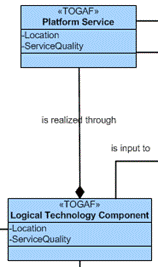
Technology Architecture Meta-Model Detail
For SOA, the Technology Architecture defines the software and hardware infrastructure needed to support the portfolio of services. A starting point for the Technology Architecture is The Open Group SOA Reference Architecture which contains most platform services possible for an SOA infrastructure. Each organization will need to customize the SOA Reference Architecture to their needs.
The Open Group has produced additional information concerning adapting an organization’s infrastructure for service-orientation, including the Service Oriented Infrastructure Reference Model which can be consulted for guidance.
Infrastructure architecture is regarded by many as one of the three pillars of information technology, together with Business Architecture and Applications Architecture. Service-oriented infrastructure results from applying the principles of service-orientation to this technology architectural pillar. It is related to SOA which is most commonly referred to as part of the application architecture pillar.
Using the models, artifacts, SOA Reference Architecture, and SOI Reference Model, the architect should develop views that enable the architect to demonstrate to stakeholders how their SOA-specific concerns relating to the Technology Architecture are addressed. Some SOA-specific models and artifacts are suggested below:
Artifact |
Purpose |
Meta-Model Entity Usage |
Logical Technology Architecture Diagram |
This diagram is used to show and analyze the instance of The Open Group SOA Reference Architecture. It will contain all architectural building blocks and capabilities deemed necessary for the SOA solution. |
Platform Service (Capability), Logical Technology Component (ABB) |
Logical Application and Technology Matrix |
This matrix is used to show and analyze the relations between the Logical Application Components and the Logical Technology Components to ensure the architect understands what technology will be used for the Logical Application Components. It will also be used to derive and validate the non-functional requirements for the Technical Components. |
Logical Application Components and their relations to Logical Technology Components including derivations of the Service Qualities. |
In addition, the standard TOGAF 9 models and artifacts should be considered.
In doing this, the architect adds further requirements to those identified in Phases A, B, and C, and addresses the requirements that can be satisfied by the Technology Architecture.
All architecture requirements should have been addressed by the end of this phase. If there are still outstanding architecture requirements, then the architect should go back to Phase B or Phase C to address them. Implementation requirements will be addressed by the projects that are identified in Phase E.
For additional information, see Appendix A. This describes changes to the standard TOGAF 9 Inputs, Steps, and Outputs appropriate for SOA. It also highlights areas of emphasis that the architect doing SOA should especially consider.
Phase E: Opportunities and Solutions
The Opportunities and Solutions phase identifies delivery vehicles (projects, programs, or portfolios) that effectively deliver the Target Architecture defined in previous phases. It reviews the target business objectives and capabilities, consolidates the gaps from Phases B to D, and organizes groups of building blocks to address these capabilities. It then generates an outline Implementation and Migration Strategy.
The identification of service and solution portfolios is a key task for SOA. The questions of what service and solution portfolios the enterprise will have, and how they will be managed, should be considered in this phase. (For the kind of enterprise SOA that we are considering here, it is quite possible that there would be a single service portfolio and a single solution portfolio.)
A delivery option that should be considered particularly for SOA is the use of services provided by external companies, as opposed to the development of services in-house or the acquisition of software products that perform the services.
The specific SOA solution is an addition to the TOGAF 9 meta-model that crosses both Phases E and F and is depicted below.

Phase E: Opportunities and Solutions Meta-Model Detail
The implementation projects that are identified, and the Implementation and Migration Strategy, will depend on the decisions taken on the level of detail of implementation specification when the architect team scoped the architecture development in Phase A.
As with the previous phases, there are a number of models, artifacts, and guidelines that are SOA-specific. Those for Phase E might include:
Artifact |
Purpose |
Meta-Model Entity Usage |
Physical SOA Solution Matrix |
This matrix shows all the components of a SOA solution. |
IS Services, Physical Application Components, Platform Services, Physical Technology Components |
Physical SOA Solution Diagram |
This diagram shows the relations between the physical SOA solution (Physical Application Components) and other solutions (Physical Application Components). It is used to show and analyze the functional and non-functional requirements of the interfaces between solutions. |
Physical Application Components and Contracts and their Service Qualities Physical Technology components and their mapping to Contracts are used for the interface mechanisms. |
Physical Service Solution Matrix |
This matrix shows which existing services are re-used, which services could be provided by external services (SaaS) and which services need to be developed as wrappings of new/existing applications and which need to be developed. It is an input to the SOA Governance Service Portfolio Management process. |
IS Services, Physical Application Components (as-is SOA services for re-use), other Physical Application Components (new and existing applications to be wrapped) and new Physical Application Components (new services to be developed or purchased externally) |
Application Guidelines |
This document provides the guidelines on how to develop the SOA solution and services. Suggestions of possible guidelines can be found in Appendix A of the SOA Governance Framework. |
|
Physical Technology Architecture diagram |
This diagram is used to show and analyze the physical technical solution for the SOA infrastructure. |
Platform Service, Logical Technology Component, Physical Technology Component |
Physical Application and Technology Matrix |
This matrix is used to show and analyze the physical infrastructure used to run the physical application on and to ensure that the non-functional requirements are derived properly and understood. |
Physical Application Components and their relations to Physical Technology Components including derivations of the Service Qualities |
Technology Portfolio Catalog |
This is a list of products and kinds of product that will be used in the implementation, including SOA run-time infrastructure, SOA development environment, service component technology, and service interface (portal, channel, etc.) technology. It will also include non-functional requirements. |
Physical Application Components and their relation with Service Qualities |
Technology Guidelines |
This document provides the guidelines on how to use SOA infrastructure. Suggestions of possible guidelines can be found in the Appendix A of the SOA Governance Framework. |
|
In addition, the standard TOGAF 9 models and artifacts should be considered.
For additional information, see Appendix A. This describes changes to the standard TOGAF 9 Inputs, Steps, and Outputs appropriate for SOA. It also highlights areas of emphasis that the architect doing SOA should especially consider.
Phase F: Migration Planning
This phase results in a detailed plan, produced in cooperation with departments responsible for concerned enterprise activities (such as the PMO, Operations, Sales and Production, Delivery, etc.), for the implementation of the architecture.
The implementation governance model is reviewed in Phase F in order to ensure that it is in place before the next phase – Implementation Governance – commences. SOA requires particular governance rules and procedures. The governance and support strategy is reviewed in the Preliminary Phase. If it needs to be updated for SOA, then this should be done before implementation starts. The architect should check in Phase F that the governance model is fit for SOA, and ensure that it has been updated if necessary before proceeding to Phase G.
Phase G: Implementation Governance
This phase involves participation of architects in implementation governance, to improve the quality of the implementations generally and in particular to ensure conformance with the architecture.
The activities performed in the Implementation Governance phase will depend in part on the decisions taken on the level of detail of implementation specification when the architect team scoped the architecture development in Phase A.
Again, as in the Preliminary Phase, the architect has a wealth of information available from The Open Group SOA Governance Reference Model. See the Introduction to SOA Governance and related sections of the SOA Source Book (first edition) for further information on SOA governance.
Phase H: Architecture Change Management
Phase H is concerned with reviewing and updating the architecture and the architecture process itself. This includes assessing the performance of the architecture and making recommendations for change.
It is at this point that the architect is likely to decide to re-visit the activities of the Preliminary Phase. Where SOA has not previously been used within an enterprise, Phase H of an architecture development is an opportunity to assess the contribution that it could make, and to consider adopting the principle of service-orientation.